limitations for flex PCBs
Unlike rigid printed circuit boards (PCBs), flex PCBs have a flexible substrate. They are made of polyester or polyimide materials and can be as thin as 12-120 microns. Conductive material traces are etched on these layers, and then a coverlay is applied to protect them from moisture, dirt, and damage.
These incredibly flexible and durable substrates allow for incredible design flexibility. They can be molded into many different shapes and are often used in devices that require a high degree of physical flexibility, such as heads-up displays for aerospace piloting or minuscule hearing aids for medical care.
flex pcbs are able to withstand high temperatures and vibrations, making them ideal for use in harsh environments like aircraft and spacecraft. They can also be bent or twisted without losing strength, which is crucial for many mobile device and wearable applications. This adaptability allows designers to create innovative products with more features and a smaller footprint.
Are there any size limitations for flex PCBs
While flex circuits can be static or dynamic, the most common are dynamic based on bending capabilities. Static flex circuits experience minimal or no bending during their operational lifespan and are typically found in consumer electronics like phones, laptops, and tablets. Dynamic flex circuits are designed to bend during operation and are commonly found in wearable devices, automotive systems, printers, and robotics. By eliminating traditional connectors and reducing the number of potential points of failure, flex circuits can improve reliability and longevity.
Aside from allowing for greater design flexibility, flex circuits are less expensive than rigid ones. This is because they can be produced in a fraction of the time, and the fabrication process itself involves significantly fewer steps. This results in significant cost savings for the product manufacturer.
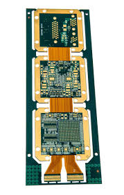
For complex designs, it is sometimes necessary to add stiffeners to a flex circuit in order to keep it rigid and stable during manufacturing. These stiffeners are usually made of FR4 and can be added to specific areas of the flex circuit in order to achieve the desired rigidity.
As a general rule, it’s recommended to avoid using solid copper in areas that are expected/designed to be bended. Instead, a hatched copper should be used, as this will increase the durability of the flex circuit and make it less likely to tear if bended repeatedly. Moreover, when designing a flex circuit, it’s vital to understand the stack-up and ensure that the thickness of the layers is correct. A simple mistake in this area can lead to the circuit not being able to be manufactured and can even result in an unusable board. To prevent this, it’s important to work with a reliable manufacturer that can provide detailed calculations of the stack-up in order to optimize manufacturing costs. PCBway offers a detailed calculator that can be used to determine how much your flex circuit will cost. This will help you plan and budget your project accordingly.